Tuesday, December 5, 2017

Arduino Project: Sound Alert via Twitter

For my second IoT project using Arduino MKR1000, I'll employ a sound sensor to send out alerts via Twitter when a loud sound is detected. This could have many uses, ranging from informing the inhabitants of a house that there is someone at the door, informing a car owner that their alarm is going off, or residents that a gunshot has gone off in their neighborhood.

See my previous posts to learn about the setup process for the Arduino MKR1000, which is wifi-enabled without any additional extensions.

I will be using the Arduino IDE to compile the code.

For hardware, I'll be using the sound sensor I purchased here, as well as my Arduino, three solder-free wires, a generic breadboard, and a Kindle power cable (this probably isn't the safest way to power Arduino, but it's what I had).

I'll be following this tutorial to set up the sound detector, as well as some code from here to utilize Twitter.

The sound setup tutorial was very simple and one of the clearest wiring guides I've ever seen. It worked so well that I have little to say about it.

My first comment is that my sound sensor has 4 pins, while the tutorial's has only 3 pins (and some I've seen elsewhere have 5!). However, this was easily overcome when I noticed that my pins are labeled A0, G, +, and DO. I'm not sure what the DO stands for, but it was pretty clear that A0 corresponds to AU0 in the tutorial, G corresponds to GND, and + corresponds to VCC.

My second comment is that I'm not sure why there are two separate code snippets given (I didn't take the time to go through the differences), but the top snippet worked for me.

Here's my working setup:


Here's some of my output (when the numbers go high, that's when I clapped my hands):


For some reason there is a delay of several seconds between when I clap my hands and when the numbers go high, but that may be because the sensor is rather cheap. I also notice that the high numbers continue for a relatively long time, as opposed to just measuring one or two high numbers (I believe a reading is being taken once per second), which is interesting.

Now with the sound sensor portion of the project working, time to move on to the Tweeting portion. I used some of the code and guidance from this source, as mentioned previously.

Here is my complete working code:

#include <WiFi101.h>
#include <Twitter.h>
int led = 13;
int threshold = 10; //Change this as desired
int volume;
//String message;
Twitter twitter("934813958439043072-RmWRNCKFCTwSm6aafgHdktL6nbUgqZD");
char ssid[] = "DG1670A92";     //  your network SSID (name)
char pass[] = "DG1670A353A92";  // your network password
int status = WL_IDLE_STATUS;     // the WiFi radio's status
void setup() {               
  /*Setup for DHT sensor*********/
  Serial.begin(1000);
  delay(300);//Let system settle
  Serial.println("Humidity and temperature\n\n");
  delay(1000);//Wait rest of 1000ms recommended delay before

  /*setup for Twitter stuff**********/
  // check for the presence of the shield:
  if (WiFi.status() == WL_NO_SHIELD) {
    Serial.println("WiFi shield not present");
    // don't continue:
    while (true);
  }
  // attempt to connect to WiFi network:
  while ( status != WL_CONNECTED) {
    Serial.print("Attempting to connect to WPA SSID: ");
    Serial.println(ssid);
    // Connect to WPA/WPA2 network:
    status = WiFi.begin(ssid, pass);
    // wait 10 seconds for connection:
    delay(10000);
  }
  // you're connected now, so print out the data:
  Serial.print("You're connected to the network");
  printCurrentNet();
  printWiFiData();

  Serial.begin(9600); // Serial port begin
  pinMode(led, OUTPUT);   
}
void loop() {

  volume = analogRead(A0); // Reads the value from the Analog PIN A0

  //Serial print level
  Serial.println(volume);
  delay(1000);
  if(volume>=threshold){
    digitalWrite(led, HIGH); //Turn ON Led
    String message = "The volume is " + String(volume);
    char msg[100];
    message.toCharArray(msg, 100);
   
    //post the temperature and humidity to Twitter
    if (twitter.post(msg)) {
      // Specify &Serial to output received response to Serial.
      // If no output is required, you can just omit the argument, e.g.
      // int status = twitter.wait();
      int status = twitter.wait(&Serial);
      if (status == 200) {
        Serial.println("OK.");
      } else {
        Serial.print("failed : code ");
        Serial.println(status);
      }
    } else {
      Serial.println("connection failed.");
    }
  } 
  else{
    digitalWrite(led, LOW); // Turn OFF Led
  }
}
void printWiFiData() {
  // print your WiFi shield's IP address:
  IPAddress ip = WiFi.localIP();
  Serial.print("IP Address: ");
  Serial.println(ip);
  Serial.println(ip);
  // print your MAC address:
  byte mac[6];
  WiFi.macAddress(mac);
  Serial.print("MAC address: ");
  Serial.print(mac[5], HEX);
  Serial.print(":");
  Serial.print(mac[4], HEX);
  Serial.print(":");
  Serial.print(mac[3], HEX);
  Serial.print(":");
  Serial.print(mac[2], HEX);
  Serial.print(":");
  Serial.print(mac[1], HEX);
  Serial.print(":");
  Serial.println(mac[0], HEX);
}
void printCurrentNet() {
  // print the SSID of the network you're attached to:
  Serial.print("SSID: ");
  Serial.println(WiFi.SSID());
  // print the MAC address of the router you're attached to:
  byte bssid[6];
  WiFi.BSSID(bssid);
  Serial.print("BSSID: ");
  Serial.print(bssid[5], HEX);
  Serial.print(":");
  Serial.print(bssid[4], HEX);
  Serial.print(":");
  Serial.print(bssid[3], HEX);
  Serial.print(":");
  Serial.print(bssid[2], HEX);
  Serial.print(":");
  Serial.print(bssid[1], HEX);
  Serial.print(":");
  Serial.println(bssid[0], HEX);
  // print the received signal strength:
  long rssi = WiFi.RSSI();
  Serial.print("signal strength (RSSI):");
  Serial.println(rssi);
  // print the encryption type:
  byte encryption = WiFi.encryptionType();
  Serial.print("Encryption Type:");
  Serial.println(encryption, HEX);
  Serial.println();
}

Notice I set the threshold to 10, which is quite low. I did this so I could snap instead of clap get results (so I wouldn't wake my roommates!).

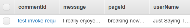
After uploading this code to my Arduino and waiting for it to connect to WiFi, here are some Tweets it sent:


And so, this project is complete! It would be simple to have alerts sent to your phone based on these Tweets if desired, and this project could have many useful IoT functions. Thanks for reading!


Monday, November 6, 2017

Arduino MKR1000 - Set Up Process

The next step of my IoT journey is to create a project using a Wi-Fi enabled Arduino. I chose the Arduino MKR1000, due to its built-in Wi-Fi capabilities. It cost around $35 plus shipping. I will also be using a connector cable that I found in the electrical lab at my university, since I realized as I started setup that I didn't have one. I would recommend purchasing one.


In this post I will record my experience setting up the Arduino and the Arduino IDE. I'll be using a Windows 8.1 PC. This is my first experience using Arduino.


I will be following this tutorial and noting all the places where there may be confusion while following it.


The tutorial uses version 1.6.8, but I will be using version 1.8.5 since it is the latest version at the time I downloaded it.


When downloading the Arduino IDE as instructed, I found it easier to use this source instead of the source given in the tutorial, since it will download an executable instead of a maze-like .zip file.


When asked to check if the driver is installed by going to the "device manager", know that the device manager is a stock application on Windows, not a part of the Arduino IDE.


Here is my Arduino MKR1000 connected to my laptop:


While uploading a sketch, I chose port COM6 instead of COM19, since that latter wasn't available in my version.


The tutorial completely skips the step about how to upload a sketch, which took me a few minutes to figure out. After selecting the proper port, you must go to Sketch -> Upload and wait for the upload to complete. When it's finished you will see the screen shown in the tutorial.


It's also unclear that you are indeed supposed to copy and paste the first code snippet under "Compile and upload your first MKR1000 Sketch" into your text editor. This is the code you need:


void setup() {
 pinMode(6, OUTPUT);
}
void loop() {
 digitalWrite(6, HIGH);   // turn the LED on (HIGH is the voltage level)
 delay(500);              // wait for 500ms
 digitalWrite(6, LOW);    // turn the LED off by making the voltage LOW
 delay(500);              // wait for 500ms
}
To verify your code, click the check mark in the upper left of the editor. I believe this is akin to 'compiling' code in languages such as C. To run the code on your Arduino, click the right-pointing arrow in the upper left-hand corner of the IDE. It is labeled "upload", and the tutorial does not specify that.


After doing so, you will see results in the black text box below the editor, and should get results similar to what I have here:


Here's what happens on the Arduino when this code runs:


I couldn't quite figure out how to verify the WIFI101 version in my IDE as the tutorial shows in Figure 11, but I believe I have the correct version (0.8.0). Since I have 0.8.0 as asked and not 0.7.0, I did not download anything from Github as recommended in that scenario.


I opted not to carry out the instructions for SimpleWebServerWiFi, as I saw no reason that it should pertain to the project I'm trying to complete. I also had no reason to enter the Troubleshooting section.


Overall, this tutorial seems to have given me a solid method to setup my first Arduino, and I feel prepared to begin my real project. I'll perform this project sometime in the coming week, and will document my experience in the next post.

Wednesday, October 18, 2017

IFTTT (part 2): Creating My Own IFTTT Recipe

In my previous post, I walked through my experience activating an existing IFTTT recipe. In this post, I'll record my process for creating a custom IFTTT recipe. This recipe will send my partner a text message whenever I leave school. I'll read through this article to gain some background knowledge on the inner workings of IFTTT.

Here are some brief notes from the article I'm reading:
- "Trigger": the this in if this, then that; invokes the action
- "Action": the that in if this, then that; invoked by a trigger
- "Recipe": a trigger and its correspond action
- "Channel": a web service or connected device that will be used in a particular recipe

I opted to not complete the tutorial in the second half of the article, as I'm interested in building a location-based recipe with the goal of sending my partner a text message whenever I leave school. I'll follow this tutorial to learn how to create such a recipe.

After reading the sections on geofencing, installing the app, and exploring existing location-based recipes, I realized that the article is over 2 years old at the time of this writing. As a result, the in-app navigation instructions are outdated, as well as their claim that "there’s no way to craft a recipe through the IFTTT mobile app". In today's version of the app, there actually is a very simple way to create a recipe. At this point, I stopped following the tutorial and instead explored the app on my own for a while. Here are the steps I took to create my custom recipe on my iPhone (the Android process is likely similar): 

1. Download the IFTTT app from the App Store and create an account, if not already done.
2. Go to the "Search" tab and search for "location".


3. Scroll down and select "New Applet".


4. Select "Location" as the trigger. This is the type of event that will cause your desired action to    occur. 


5. Choose "You exit an area".


6. Adjust the map so that your desired exit area is selected, then click "Save". This is the geofence that will trigger your action when you exit it. 


*Note that you will have to allow IFTTT to access your location at all times in order for any location-based recipe to work. 


7. Select SMS as the action service, then select "Send me an SMS". This will allow the recipe to send an SMS to a number of your choosing whenever the trigger event (in our case, leaving a designating location marked by our geofence) occurs. 


*Note that originally, the recipe will be configured to send to your phone number (assuming you have already provided IFTTT with it). To change this, simply click inside the applet and erase your phone number, then enter your desired phone number. You can also modify the rest of the recipe name as desired. 


8. Click "Finish", then make sure your newly minted IFTTT recipe is on. 


Congratulations, you now have a fully functional, location-based IFTTT recipe! Now test out the functionality by leaving your designated geofence area and see that your entered phone number receives an SMS. 

I won't be leaving the area I designated until at least late afternoon today, so I'll post an update here with whether or not the recipe worked as well as a screenshot of the results.

Thanks for reading! My brief journey into IFTTT was enlightening, and I can forsee many opportunities to integrate IFTTT into future IoT projects. The next stage of my IoT journey will be delving into the expansive and exciting world of Arduino using internet capabilities. I plan to make my first post on this subject sometime in the next week or so (depending on when my supplies arrive), so be on the look out for my next post!

UPDATE: Here's the message my roommate received when I left the area:


Friday, October 6, 2017

IFTTT (Part 1): Using a pre-existing IFTTT recipe

Besides AWS, another useful service for various IoT projects is IFTTT (If this, then that). This allows users to make one internet-enabled action trigger another internet-enabled action. For example, every time I take a picture on my iPhone, upload it to Dropbox.

I'm not planning to spend much time on this service, just enough to get my feet wet. In this post I'll document my experience using an existing IFTTT recipe, then I'll create my own IFTTT and document that process in a subsequent post.

After doing some research about IFTTT, I discovered that my city (Louisville, KY) has it's own set of custom-built applets. After scrolling through the numerous applets, one stood out: "Retrieve Air Quality and notify by SMS on change". It sends the user a text message every time the air quality level in the area changes. That sounds useful to me since I know the city has low air quality from time to time, and I don't want to be doing any cardio activities outside during those  times if possible.


After flipping the switch to the "On" position, I was prompted to enter  my phone number and the verification cod that was sent with it. 


After doing this, I wasn't sure if the function had been activated. Going to my applet dashboard, it appears that it has been activated.


However, I haven't yet received a text from the service. I'll update this post as soon I receive something. In the meantime, I'll begin building a custom IFTTT function! Check back soon for my post about the process. 


Update: Around 30 minutes after I activated the IFTTT applet, I received a second text with the following information: 


Pretty cool! I think I'll keep this activated for my personal information. However, I wish there was a way to get this emailed to me instead, as multiple texts per day from this service may get annoying. Regardless, this could prove to be a very useful function. 

UPDATE: After a day of having this feature on, I've decided to only turn it on for certain occasions. The reason for this is that the air quality changes so frequently (~once per hour, as seen in the screenshot below) that the constant notifications were bombarding my phone. I still think the feature is neat, but maybe it would be better if I program my AWS IoT Button (see previous posts) to send me a text with the current air quality whenever I press it, allowing me to only see the information when I want to see it. 


Wednesday, September 27, 2017

AWS IoT Button (2nd gen.): sending an SMS message

I recently purchased an AWS IoT Button (2nd generation), which can be found here for $20. This is basically a physical button that connects to wi-fi and easily integrates with AWS applications, especially Lambda.


To set  up my button, I followed the process here. I opted for to download the iOS app to ensure the easiest setup process.

The first time I tried setting up the button, I couldn't connect it to wi-fi (so it was useless). I tried several different networks, to no avail. Seeing no other options, I gave it a rest and tried again the next day. With no apparent change to my network or setup process, the button connected as intended.

At the end of the mobile app-based setup process, I was prompted to set a Lambda function that will be executed when the button is clicked. I chose the preset function to send an SMS message using Python. (Note: This function will appear in your Lambda console and can be edited in any way.) I entered my cell phone number and desired message, then tested my button.


Viola! I received a text message from my button with the message I set. (I tested the button a few more times, just to make sure.)


Here's a video demonstration of my results: 


This functionality may be simple, but I can imagine it being used in a variety of settings, from hospitals and hotels to restaurants and airplanes. More importantly, this exercise laid the foundation for me to create more complex functions in the future.

Monday, September 18, 2017

Reading from and Modifying a DynamoDB Table using API Gateway

In many IoT (Internet of Things) projects, it is necessary to read from and write to a database. AWS has an application called DynamoDB that is a NoSQL database, exactly what we need. While it is very simple to add/modify/delete entries in this database via the user interface, it's not so obvious how to do so via HTTP API calls.

So, in this post I'll continue the AWS portion of my journey into IoT to learn how to do just that. I'll be following this tutorial.

The first thing I encountered is I wasn't sure if I was supposed to follow the steps under "Defining APIs", or if that was just knowledge for later. Turns out, that was knowledge for later. If I had any prior experience with APIs I probably would have realized this. Basically, the "API definition"s are just a high-level plan for what you want your API requests to look like in the end. In my opinion this information should go in the "Creating the APIs" section.

Moving through "Creating the DynamoDB Table", I experienced no trouble.

Under the subheading "Creating the Post Comments API", the instruction begins from what's called the "editor screen". There's a screenshot, but no indication of how to make that screen appear. I figured out that you must click "Actions" before you can select "Create Resource".


Similarly, the "Create Method" option is in this drop down, which is needed in the next step but the tutorial doesn't explain how to get there. 

The tutorial also asks us to create an IAM role that "has permission to call the DynamoDB API PutItem for the Comments table", but doesn't explain how to do so. Looking at some other AWS documentation I took the following steps: 
  1. From the AWS Console, go to the IAM service. 
  2. Select "Policies" on the left panel.
  3. Select "Create a Policy".
  4. Choose "Select" by "Copy an AWS Managed Policy". 
  5. Choose "Select" next to "AmazonDynamoDBFullAccess"
  6. Choose "Create Policy". 
Honestly, I'm not sure if it's appropriate to use the AmazonDynamoDBFullAccess policy, but I don't know what else to use. 


The next issue I ran into was that when I tried to test the API using the response body provided in the tutorial, I get a message with a response body of "internal server error". To verify that the request to post a new item didn't work, I navigated to the DynamoDB table and, sure enough, no item was added. Looking at the logs generated from the execution, I see "Execution failed due to configuration error: API Gateway does not have permission to assume the provided role". I suspect this an issue with the IAM role I assigned. 

SOLUTION: 
After scouring the internet for an answer, I finally resorted to post a question on Stackoverflow. After creating the policy as outlined above, you must take the following steps: 

  1. Go to "Roles" and click "Attach Policy". 
  2. Select the policy you just created and click "Attach Policy".
  3. Copy the value of "Role ARN", located near the top of the page. 
  4. Go to your API in API Gateway and click the method you are working on (in my case, "Post").
  5. Click "Integration Request".
  6. Click the edit icon next to "Execution Role" and paste the role ARN inside. 
  7. Click the small check mark next to the text box, and you should be good to test your API. 

Upon successful completion of a POST request, you should see Successfully completed execution near the bottom of the logs output. To verify that the request was successful, I went to my DynamoDB table and sure enough, a new entry had been inserted!


The GET request implementation went smoothly. Upon success, I received the following log output (partial): 
Mon Sep 18 21:29:34 UTC 2017 : Endpoint request body after transformations: {
    "TableName": "Comments",
    "IndexName": "pageId-index",
    "KeyConditionExpression": "pageId = :v1",
    "ExpressionAttributeValues": {
        ":v1": {
            "S": "breaking-news-story-01-18-2016"
        }
    }
}
Mon Sep 18 21:29:34 UTC 2017 : Sending request to https://dynamodb.us-east-1.amazonaws.com/?Action=Query
Mon Sep 18 21:29:34 UTC 2017 : Received response. Integration latency: 32 ms
Mon Sep 18 21:29:34 UTC 2017 : Endpoint response body before transformations: {"Count":1,"Items":[{"userName":{"S":"Just Saying Thank You"},"message":{"S":"I really enjoyed this story!!"},"commentId":{"S":"test-invoke-request"},"pageId":{"S":"breaking-news-story-01-18-2016"}}],"ScannedCount":1}


That concluded the end of the tutorial. 

Here is a video demonstration of my results: 


Knowing how to perform GET and POST operations on a DynamoDB table will prove invaluable in the exploration of IoT. All sorts of data can be stored and retrieved by devices, available to query and analyze to unearth valuable insights about the world around us. 

Tuesday, September 12, 2017

Learning AWS Lambda, API Gateway, and DynamoDB

The first step I'm taking in my IoT journey is to learn about Amazon Web Services (AWS). Many IoT products utilize (or can utilize) this service, which is why it seems like a good starting place. Cloud computing is essential to IoT, since very little processing is done at the local level (hence: "internet").

If you aren't aware, AWS is a serverless platform that allows developers to run code, build databases, and much more all in the cloud. There are several advantages to using AWS:


  • frees developers and businesses up from having to administer to their own servers, since Amazon takes care of all server maintenance
  • virtually unlimited scaling, since AWS will dedicate more or fewer servers as needed for your data
  • only pay for the time when your code is called (in the case of AWS Lambda) -- not idle time

To get started, I followed these tutorials. They walk you through how to set up an AWS account and the AWS CLI (Command Line Interface), as well as how to use the Lambda, API Gateway, and DynamoDB services. All of these are basic services that will be essential in many IoT projects

After completing the first step in the tutorial (I already had an AWS account), I have the AWS CLI installed, which means I can use the Windows Command Prompt to efficiently perform AWS-related tasks. So far I've used it to configure an IAM (Identity and Access Management) role, configure my root account, and list all of the Lambda functions in my account.

After completing the second step in the tutorial, creating a hello-world style Lambda function, I now understand the basics of working in the Lambda console. I can save and test function code, and modify and utilize key-value pairs as function input. I can also analyze the output of running a function.

While completing the third step in the tutorial, creating a microservice using Lambda and API Gateway, I came across a couple of issues. First of all, I was confused about the part that says "create a DynamoDB table with streams enabled". While setting up the DynamoDB table, there didn't seem to be an option to enable streams. I simply saw this screen:
There's nothing about "streams" on there. Wanting to get my table set up correctly, I scoured the internet for a solution, to no avail. I finally decided to go ahead and click "Create", although I had no idea if my database would be set up properly. It was then that I realized that streams can only be enabled after creating the database. In the screen below, you have to click "Manage Streams"...


And then choose an option. Any option will enable streams, but beyond that more research may be required to determine which option will be best for your purposes. I left it at the default option.


Other than that, I didn't have any trouble following AWS's tutorial. However, the end was quite anti-climactic. It shows you how to send an HTTP GET request to your function by pasting the request in the test event configuration. The result was basically nothing, since I didn't have anything in my DynamoDB Table.


So, I decided to do some research to see how to insert new rows via HTTP requests. (You can also insert new rows through the user interface, but I thought doing so programatically may be more useful for IoT projects.) It appears this is the request syntax for updating a DynamoDB table. After attempting to use it, I've decided to make a subsequent post dedicated to that topic solely. 


Another thing that didn't click for me at first was the role API Gateway played in the architecture. You can see the connection by going to the API Gatway console, selecting the ANY function, and clicking Test. 

Then, choose the GET method (or whichever method you prefer; results may vary). In Query Strings, you can set any key-value pairs that your function uses. For example, I typed TableName = MyTable. Select "Test", and your API will call your Lambda function and show you the same output you would see testing it in the Lambda console. 


Here is a video demonstrating my results: 


Overall, I think this was a very successful first step for me into the world of IoT. I'll be able to use these basic AWS technologies in countless projects as I learn about the new tools we developers have at our disposal today. 

Tuesday, August 29, 2017

Pilot Post

In this blog, I will post updates, demos, and documentation of projects I work on, as well as useful resources that I find while I start exploring the amazing world of IoT (Internet of Things). 

I hope material posted here will provide insight, inspiration, or help to everyone who reads it.

This is the first post in this blog.